Or a little bit of theory that’s useful to know, but don’t worry about the equation appearing below – no maths required!

Please don’t be concerned about the mathematical appearance of this note unless you are that way inclined. The important message to take out of this section is that the infusion process is governed mainly by 5 variables which can often be manipulated to overcome infusion problems and optimise infusion outcomes. When you experience an infusion problem, please revisit this law to see which variables you can change to influence the process.
The flow of liquid through a porous medium is described by a relationship known as Darcy’s Law. While this relationship was discovered by the Frenchman Henri Darcy as the result of his study of the flow of water through underground aquifers, it also holds true for the flow of resin through porous laminates. Darcy’s law can be written as the equation:
Q = K A Δp
µ L
Where:
Q = volume rate of flow
K = permeability of the material (a measure of the ease that resin can flow through the material)
A = area of the cross section through which the resin is flowing
Δp = pressure difference across a section of laminate whose length is L
µ = (dynamic) viscosity of the resin
L = distance the resin has to travel
Without getting involved in the maths at all, let’s have a look the significance of the variables that make up Darcy’s law.
The critical importance of resin viscosity (µ) – and how temperature influences this
Q = K A Δp
µ L
Darcy’s Law tells us that rate at which a resin will flow through a laminate is inversely proportional to µ, the viscosity of the resin. In other words, a low viscosity resin will flow faster through the dry laminate. Conversely, a high viscosity resin will flow more slowly. While this may seem blindingly obvious, in practice the significance of resin viscosity is often missed. Infusion grade resins typically have a viscosity lying between 200 and 500 centipoise (standard abbreviation cP, but often written cps) at 20 0C (68 0F). In SI units, resin viscosity might lie between 0.2 and 0.5 Pa s.
Compared with water, which has a viscosity of 1 cP at the same temperature, infusion resins will move somewhere between 200 and 500 times slower than water would under the same conditions. Clearly, resin viscosity has a very significant influence over the infusion process. While the relatively high resin viscosity must be considered when infusing, perhaps of more practical concern are the consequences arising from variations in viscosity.
For example, changing from one make of resin to another may lead to substantially different infusion flow rates. Even changing one component of a resin system from the same supplier may change the viscosity of the mixed resin significantly. The length of storage can also affect resin viscosity. Resin stock should be rotated so old stock is used first.
Another reason for significant differences in infusion outcomes is viscosity variation arising from temperature change. For example, it is often forgotten that resin viscosity is a function of both its temperature and state of cure. An infusion resin formulated for use at 20 0C (68 0F) may more than double in viscosity if infused at 10 0C (50 0F). Clearly, this relatively small temperature change will make a big difference to the rate at which resin will infuse through the dry stack of material. Maybe your composite shop is nicely temperature controlled, but is your resin stored at that temperature, too? Or did you just bring it in from the dangerous goods store where it has been sitting at just above freezing? Have your mould and all of your laminate materials also been stabilised at moulding temperature? If any aspect of the process is not at the temperature the resin manufacturer formulated the resin for, you risk an infusion that will not flow as anticipated.
Moral of the story according to Darcy:
- Use a resin formulated for infusion – not a high viscosity resin for hand lay-up
- Be consistent with resin system selection, or be prepared to change the infusion configuration to accommodate different resin systems
- Be aware of temperature effects. Temperature can have a significant influence on viscosity.
Nature abhors a vacuum – or Δp, the driving force for infusion
Q = K A Δp
µ L
For most flexible bag infusion processes, Δp is normally considered to be the vacuum level measured on the vacuum gauge, either on the resin trap or at the vacuum pump. In fact, Δp is a little more complex than that. Assuming that the vacuum gauge is accurate (which many aren’t), Δp is the end result of:
Gauge vacuum
Minus pressure losses from air leaks into the bag, or into the vacuum system
Minus the resistance to air flow in the laminate between the vacuum connection to the bag and the resin front
Minus the resistance to resin flow in the tube from the resin supply to the part
Plus or minus the static pressure head of the column of liquid resin. If the resin supply is above the part Δp will be increased. If the resin supply is below the part Δp will be decreased.
In considering how Δp might be manipulated to achieve a different infusion result, bear in mind that Δp, the infusion driving force, is not just the reading shown on the vacuum gauge. For example, if resin flow is too fast to achieve complete wet-out of the laminate, reducing the vacuum level is not necessarily the best flow control option, as this may loosen the bag. As alternatives, consider restricting the resin flow from the resin supply (by part closing a valve, or gently clamping the resin feed line), or by lowering the resin supply (or raising the part, relative to the resin supply).
How understanding the principle of Transverse Flow allows advantage to be taken of K, A and L.
Q = K A Δp
µ L
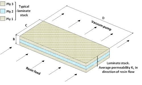
The flow of resin through a section laminate stack of uniform permeability in the direction of resin flow can be simplified to the following:

In this case, the variables to be plugged into Darcy’s Law are:
Permeability K = KC, the permeability measured in the C-axis direction
Cross section area resin is flowing through is B x D. In the Darcy equation, A = B x D
Resin flow direction is parallel to the C-axis. In the Darcy equation, L = C
Clearly, the flow of resin through a laminate could be improved, if:
- K, the permeability of the laminate could be increased
- A, the cross section through which the resin has to flow could be increased
- L, the distance the resin has to flow could be decreased.
At first glance, it might seem that these parameters are unchangeable for a particular laminate stack placed into a specific mould. However, if a layer of much more permeable material (flow medium) can be placed adjacent to, or within, the dry stack to be infused the pattern of flow into a laminate can be beneficially altered.
The idea of placing the flow medium outside the dry stack appears to have originated with Bill Seemann of Seemann Composites in the late 1980’s/early 1990’s, culminating in the SCRIMP patent. Alternative developments placed the flow medium within the dry stack. We will now consider how the use of a flow medium in either of these locations can radically alter the Darcy variables K, A and L.
Placing the high permeability flow medium OUTSIDE the laminate stack to be infused
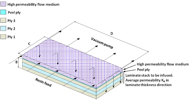
Let’s consider the case where a high permeability flow medium layer is placed above the dry stack we wish to infuse. As long as the flow medium remains permeable while compressed under vacuum, it will preferentially fill with resin. The resin flow pattern into the laminate we want to infuse will now look like this:

Q = K A Δp
µ L
Permeability K (of the laminate stack) = KB, the permeability measured parallel to the B-axis
For most fibre based reinforcements KB (the permeability at right angles to the plane of the fibres) is considerably less than KC (the permeability in the plane of the fibres). While changing the resin flow direction so that it is largely perpendicular to the plane of the fabric would appear to be the wrong thing to do, we will soon see that this disadvantage is overcome by significantly greater improvements to A and L.
Cross section area resin is flowing through (into the laminate stack) is C x D. In the Darcy equation, A = C x D
Since dimension C will usually be much greater than dimension B, the area available for resin flow into the dry stack will be similarly greater. According to Darcy, resin flow into the laminate will be improved proportionately.
Resin flow direction (through the laminate stack) is parallel to the B-axis. In the Darcy equation, L = B
Since the thickness of most laminates is small, L will be small. Because L is on the bottom of Darcy’s equation, resin flow into the laminate will be improved significantly.
Placing a high permeability flow medium outside the surface of a laminate stack to be infused allows resin to infuse into the laminate via its entire surface area, rather than the usually much smaller cross-section area. Changing the resin flow direction through the laminate in this manner results in TRANSVERSE FLOW.
If the high permeability flow medium is placed outside the structural laminate, it is usually removed after the resin has cured. To make this possible, a finely woven tough fabric is usually placed between the flow medium and the laminate stack. This layer is called peel ply. Removing the peel ply from the cured laminate will also remove the flow medium. Removal of the peel ply will leave one roughened surface on the laminate. This roughened surface is usually ideal for secondary bonding.
Note that the flow medium may have a preferred flow direction. In cases where it is desirable to either speed up or slow down the rate of resin flow through the flow medium, try reorienting the flow medium.
Placing the high permeability flow medium INSIDE the laminate stack to be infused
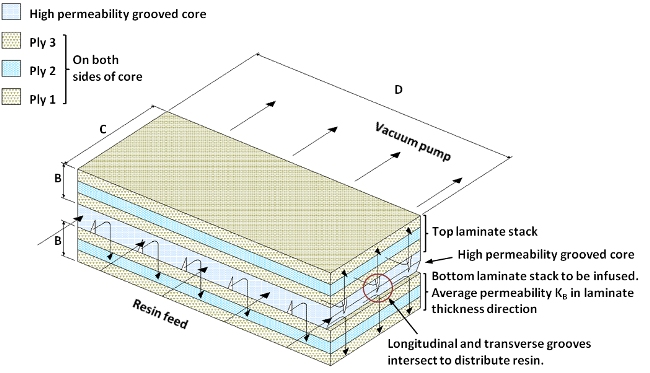
Another way to achieve the benefits of transverse flow is to place the high permeability flow medium somewhere within the laminate and leave it there after the resin has cured. Again, as long as the internal flow medium retains high permeability while under vacuum, the flow medium will preferentially fill with resin. The resin flow pattern into both sides of the laminate stack to be infused will behave as illustrated below. Note that while the illustration shows one relatively thick grooved core as the internal flow medium, the internal flow medium can be a wide range of materials. It can also be in more than 1 layer.

The Darcy’s Law effects will be just the same as for the externally positioned flow medium, except that flow distance L can potentially be further reduced.
Internal flow mediums are designed to remain within the laminate stack and become part of the final laminate. Appropriately selected internal flow layer(s) can enhance other laminate properties such as stiffness and impact resistance. Using an internal flow medium will, however, always make a laminate heavier.
Summing up
- Directly proportional to material permeability, the laminate area perpendicular to resin flow and the driving pressure. Hence, increasing the values of these variables will improve flow.
- Inversely proportional to resin viscosity and the length of the flow path. Hence, decreasing these variables will improve flow. If an infusion does not go as planned, consider how you might manipulate one or more of these variables.
Acknowledgement
We thank Chris Hickey of the Centre for Advanced Composite Materials for his advice on this topic. For information on the activities of CACM, please visit http://www.cacm.auckland.ac.nz/uoa/.
Feedback or queries on this note?
We are keen to improve the accuracy and value of Vacman’s Notes. If you have any feedback or queries regarding this note, or would like to suggest new topics to be covered, Vacman would be pleased to hear from you! Please comment below! Or email [email protected]
