When using the resin infusion process to make a composite part, the combination of a peel ply resin break (although maybe it should be called a resin brake?) and a segmented vacuum line around the perimeter of the laminate can deliver the following benefits:
- Improved control over the resin distribution pattern
- Reduced resin wastage
- Reduced risk of resin trap overflows
- Less vacuum tubing wastage and reduced resin trap cleaning.
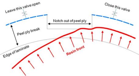
The purpose of the resin break is to significantly slow down the speed of resin movement as soon as the resin has filled to the edge of the laminate. This allows the laminator more time to confirm that the laminate is completely filled. The reason for segmenting the perimeter vacuum line into zones is to allow the laminator to influence the pattern of resin filling.
The general arrangement is illustrated below. The layer of peel ply typically placed between the top surface of the laminate and the flow medium is extended beyond the edge of the laminate by a distance that might range from 30 mm (1¼”) for a small part through to 100 mm to 150 mm (4” to 6”) for a large part such as a boat hull or wind blade. Note that for any particular part, the width of the peel ply break should be uniform around the perimeter. At intervals, small areas of peel ply are cut away and the perimeter spiral-cut vacuum line under the bag film is interrupted to match the notches in the peel ply. For small parts, a 75 mm (3”) gap between each section of perimeter vacuum line appears to be sufficient to isolate one section of vacuum line from the adjoining one. For large and complex parts, better process control could be achieved by increasing the gap between sections to about 300 mm (12”). At this time, we can’t be completely specific about optimum gaps and welcome feedback from hands-on laminators using these techniques.

Each section of perimeter vacuum line must have its own exit from the vacuum bag. This external vacuum tube can be fitted with a valve as shown, or be of sufficient length to allow it to be clamped off without stressing the penetration through the bag. If the resin trap has sufficient vacuum connections on its lid, each of these external lines can be run directly to the resin trap (left hand illustration below). If the resin trap lid does not have sufficient connections, external lines may be grouped together via Tees, as in the right hand illustration. Having each vacuum line run directly to the resin trap allows optimum process control.

Controlling resin flow through a laminate
If the resin front is moving too fast towards a section of the perimeter, or if the resin enters the peel ply resin break of a zone, the external valve for that zone should be closed or the tube clamped off. If zones are closed off as they fill with resin, the discharge of resin from the part can be completely avoided. If difficulty is encountered filling a particular portion of the part, vacuum can be maintained on the appropriate zone(s) until resin filling is complete.
Overcoming the slower evacuation time resulting from the use of peel ply breaks
While the peel ply resin break beneficially slows the speed of resin flow once the laminate is full, it also slows the initial rate of air evacuation from the part. This is of no consequence towards the end of an infusion, because air flow movement is minimal at that stage, but a wide break may noticeably slow initial evacuation of the bag. To overcome this, and potentially deliver other benefits, we recommend a supplementary vacuum line from the resin trap to the resin feed side of the part. See illustration below. Before admitting resin to the part, valve 1 under the resin feed bucket is closed. Valve 2 on the supplementary vacuum line is open and the perimeter vacuum valve(s) 3 are open.
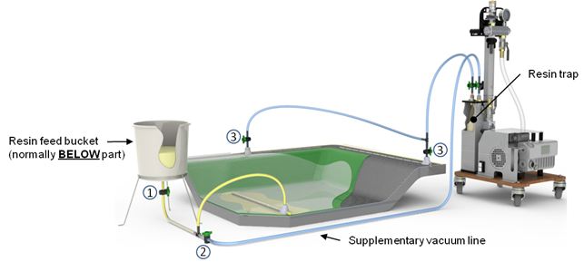
After evacuating the laminate and leak checking the bag, valve 2 is closed. Perimeter valve(s) 3 remain open and the resin valve 1 is opened.
An additional benefit may be derived from the supplementary vacuum line after the part has been filled with resin – as long as the resin has not gelled. To derive this benefit, close the resin valve 1 and open valve 2. Any excess resin remaining in the resin feed part of the laminate will be drawn out through the supplementary vacuum line towards the resin trap. Please note that it may be necessary to use a reduced vacuum level when the supplementary vacuum line is reopened to avoid the laminate becoming “dry” in the resin feed area. This dry appearance may result from vapour emission with some resin types (e.g., polyester or vinyl ester), and possibly the expansion of residual air bubbles that have been entrained in the resin at atmospheric pressure. While needing to be done with care, re-applying vacuum to the resin feed side of an infused part is worth considering if the goal is the least possible weight infused part.
*For feeding degassed resin please refer to separate note Feeding degassed resin to infused parts
Feedback or queries on this note?
We are keen to improve the accuracy and value of Vacman’s Notes. If you have any feedback or queries regarding this note, or would like to suggest new topics to be covered, Vacman would be pleased to hear from you! Please comment below! Or email [email protected]